Answer
Jun 21, 2018 - 09:52 AM
You should copy and paste the definition of your module and rename it. if you do what I said you can modified each one independently
Rgards
Hasan
By on 6/21/2018 3:06:15 PM | Like (0) | Report
Could you please share ONLY one MMC including VDC control?
By on 6/21/2018 3:12:40 PM | Like (0) | Report
Hasan, I don't understand you?
By on 6/21/2018 3:16:00 PM | Like (0) | Report
Could you please send me one terminal of MMC on Vdc control including balancing DC voltage?
By on 6/21/2018 3:31:50 PM | Like (0) | Report
I am not able to attach a file. So, here's the link of the IEEE paper that I am referring to.
https://ieeexplore.ieee.org/document/7523209/
By on 6/26/2018 9:41:23 AM | Like (0) | Report
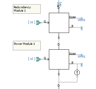
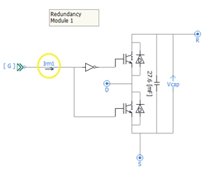
Hello Hasan, I need to measure the current entering the Sub module of the MMC that I am currently designing. I know that I need to place a Current meter in series with a wire and then use the same name on the data label to access it. However, when I place the Current Meter in Series and Run the Simulation, I am getting the following errors for the same current meter.
1. "Description
Invalid TO branch node '$N1' "
2. "Description
Unresolved branch at -> $CBR:BN"
It would help me if you could shed some light on this.
Regards
Sudarshan.
By on 6/26/2018 1:05:12 PM | Like (0) | Report
It is hard for me to till you what is going on, but keep in your mind the connection point dimensions
By on 6/26/2018 3:11:50 PM | Like (0) | Report
Hello,
What connection port dimension?
By on 6/28/2018 11:47:58 AM | Like (0) | Report
Try to put small resistance or move and arrange your
model element
By on 6/28/2018 6:03:10 PM | Like (0) | Report
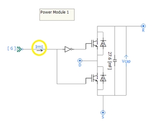
You are measuring the gate signal not the current ;)
By on 6/28/2018 6:07:34 PM | Like (0) | Report
No, I need the current measurement for the control architecture.
By on 6/28/2018 6:11:03 PM | Like (0) | Report
Put your ammeter out of the module
Add New Comment 


Add New Comment