Answer
This question has not yet been answered.
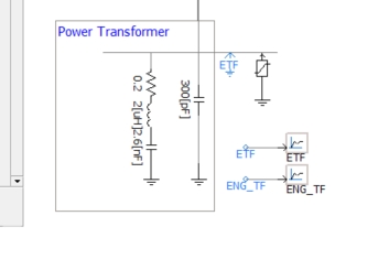
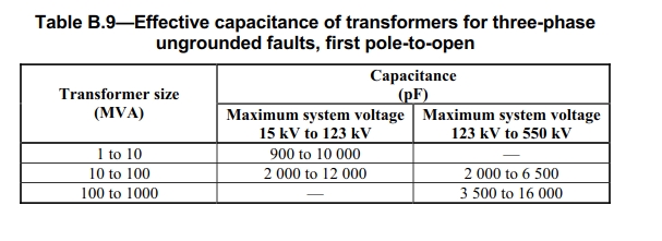
I would like to know how the transformer model was derived for the PSCAD lightning transient OV study example. The transformer was represented with 2 capacitances, a resistance and an inductance. What is this inductance used for the model and how was it gotten. Also, how were the 2 capacitances of the transformer derived. IEEE C37-2011 shows transformer capacitance for MVA ratings in table B.9 (it is a single value). How is there 2 transformer capacitances in the pscad model. What are this capacitances and how can i get/estimate them without a transformer datasheet.
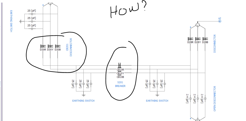
The disconnect switches and breakers were also represented as transmission lines. I will like to know how their travel time and surge impedance was derived.
Lastly, the tower footing resistance was varied in the example. Was this to illustrate the effect of tower footing resistance only? Also, can i replace this effectively with a single value of the the substation grounding grid (resistance of ground electrodes). I know the range of values so can i use the smallest value only so i get worst case scenario? ce
ce

lightning sudy, power transformer modelling, insulation coordination, hgih frequency modelling
Do you have the same question? Follow this Question
This question has not yet been answered.
We look to ensure that every question is answered by the best people with relevant expertise and experience, the best answers include multiple perspectives. Do you have relevant expertise or experience to contribute your answer to any of these commonly asked questions?

By
I look forward to your response.
Add New Comment