Answer

Jul 25, 2015 - 07:45 AM
Hi there
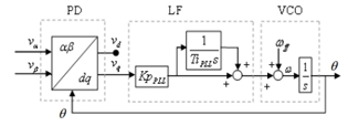
PLL for Synchronization of θ A phase-locked loop (PLL) is a synchronization control system that generates a signal that has a fixed relation to the phase of a reference signal. A phase-locked loop circuit responds to both the frequency and the phase of the input signals, automatically raising or lowering the frequency of a controlled oscillator until it is matched to the reference in both frequency and phase. The PLL block diagram shown in Figure below consists of three basic functional blocks which is the phase detector (PD), a loop filter or proportional-plus-integral controller (LF) and a voltage controlled oscillator (VCO). The PLL constantly tracks the phase of the line voltage ac 1 u for orientation of the direct (d) and quadrature (q) axis reference frame in which the other controllers rotate.
 The phase detector is a circuit capable of delivering an output signal that is proportional to the phase difference between its two input signals. In the scenario shown in Figure below the PD compares the phase of the input reference signal to be tracked, (wt +theta) , to the phase given by the voltage controlled oscillator (VCO),theta . The two input signals (valpha) and (vbeta) are orthogonal (i.e. 90 degrees shifted in phase) and expressed as in equation.
 Where ω is the instantaneous angular frequency of the input signal. The phase detector block is modelled in PSCAD as equation 4, which is the αβ to dq transformation block for the voltage and current in Figure 1, is the so called Park transformation.
  The transform from one complex coordinate system to another complex coordinate system, creates a local reference frame rotating with the fundamental frequency given by the VCO as shown in equation (3). In this rotating frame, the direct axis component Ud1 should be in phase with the fundamental of the input signal Uα1 as Uq is controlled to zero by the PLL. This means that the quadrature axis component Uq should be equal to zero, which is taken care of the proportional-integral effect of the loop filter (LF).
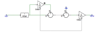
  The figure above shows the PLL model as implemented in PSCAD. When modeling the PLL Integrator in PSCAD an integrator reset that will avoid problems due to integrator windup is included. The frequency (wff=2*pi*f)added in the VCO is a feed forward of the fundamental of the input signal Uα in order to initialize the PLL and reduce the pull-in time. The phase output from the PLL is often only running from 0 to 2π (modulus 2π) as it else will cause overflow in the control system as times goes towards infinity.
Regards
Hasan
PLL for Synchronization of θ A phase-locked loop (PLL) is a synchronization control system that generates a signal that has a fixed relation to the phase of a reference signal. A phase-locked loop circuit responds to both the frequency and the phase of the input signals, automatically raising or lowering the frequency of a controlled oscillator until it is matched to the reference in both frequency and phase. The PLL block diagram shown in Figure below consists of three basic functional blocks which is the phase detector (PD), a loop filter or proportional-plus-integral controller (LF) and a voltage controlled oscillator (VCO). The PLL constantly tracks the phase of the line voltage ac 1 u for orientation of the direct (d) and quadrature (q) axis reference frame in which the other controllers rotate.
 The phase detector is a circuit capable of delivering an output signal that is proportional to the phase difference between its two input signals. In the scenario shown in Figure below the PD compares the phase of the input reference signal to be tracked, (wt +theta) , to the phase given by the voltage controlled oscillator (VCO),theta . The two input signals (valpha) and (vbeta) are orthogonal (i.e. 90 degrees shifted in phase) and expressed as in equation.
 Where ω is the instantaneous angular frequency of the input signal. The phase detector block is modelled in PSCAD as equation 4, which is the αβ to dq transformation block for the voltage and current in Figure 1, is the so called Park transformation.
  The transform from one complex coordinate system to another complex coordinate system, creates a local reference frame rotating with the fundamental frequency given by the VCO as shown in equation (3). In this rotating frame, the direct axis component Ud1 should be in phase with the fundamental of the input signal Uα1 as Uq is controlled to zero by the PLL. This means that the quadrature axis component Uq should be equal to zero, which is taken care of the proportional-integral effect of the loop filter (LF).
  The figure above shows the PLL model as implemented in PSCAD. When modeling the PLL Integrator in PSCAD an integrator reset that will avoid problems due to integrator windup is included. The frequency (wff=2*pi*f)added in the VCO is a feed forward of the fundamental of the input signal Uα in order to initialize the PLL and reduce the pull-in time. The phase output from the PLL is often only running from 0 to 2π (modulus 2π) as it else will cause overflow in the control system as times goes towards infinity.
 Regards
Hasan


Add New Comment